Magnetic Materials:
- Materials which are attracted by magnets are called magnetic materials and those materials which are not attracted by magnets are called non-magnetic materials.
- There are a number of materials that can be attracted by magnets.
- These can be magnetised to create permanent magnets.
- Magnetic materials can be categorised as magnetically hard or magnetically soft materials.
- Magnetically soft materials are easily magnetised.
- Magnetically hard materials also can be magnetised but they require a strong magnetic field to be magnetised.
- It is because materials have different atomic structure and they behave differently when they are placed in a magnetic field.
- Based on their behaviour in a magnetic field they can be classified as below.
Diamagnetic Materials:
- When suspended in an external uniform magnetic field they will align themselves perpendicular to the direction of the magnetic field.
- They have a tendency to move away from the stronger part to the weaker part when suspended in a non-uniform magnetic field.
- They get magnetised in a direction opposite to the magnetic field.
- Examples for diamagnetic substances are bismuth, copper, mercury, gold, water, alcohol, air and hydrogen.
- Magnetic character of these substances is not affected by the external temperature.
Paramagnetic Materials:
- When suspended in an external uniform magnetic field they will align themselves parallel to the direction of the magnetic field.
- They have a tendency to move from the weaker part to the stronger part when suspended in a non-uniform magnetic field.
- They get magnetised in the direction of the field.
- Examples for paramagnetic substances are aluminium, platinum, chromium, oxygen, manganese, solutions of salts of nickel and iron.
- Magnetic character of these substances is affected by the external temperature.
Ferromagnetic Materials:
- When suspended in an external uniform magnetic field they will align themselves parallel to the direction of the magnetic field.
- It has a tendency to move quickly from the weaker part to the stronger part when suspended in a non-uniform magnetic field.
- They get strongly magnetised in the direction of the field.
- Examples for ferromagnetic substances are iron, cobalt, nickel, steel and their alloys.
- Magnetic character of these substances is affected by the external temperature. When they are heated they become para magnetic.
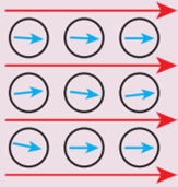
Comparison of Types of Magnetism | |||||
Type of magnetism | Magnetising field is absent (H = 0) | Magnetising field is present | Magnetisation of the material | Susceptibility | Relative permeability |
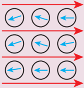
Diamagnetism |
|
| 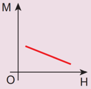 | Negative | Less than unity |
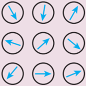
Paramagnetism |
(Net magnetic moment but random alignment) |
(Aligned with the field) | 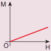 | Positive and small | Greater than unity |
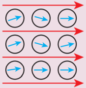
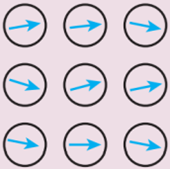
Ferromagnetism |
(Net magnetic moment in a domain but they are randomly aligned) |
(Aligned with the field) | 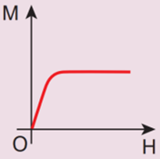 | Positive and large | Very large |
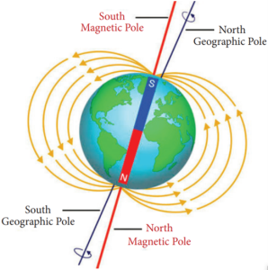
Earth is considered to be the largest dipole magnet:
- Earth has been assumed or imagined by the scientists as a huge magnetic dipole.
- However, the position of the Earth’s magnetic poles is not well defined in the Earth.
- The south pole of the imaginary magnet inside the Earth is located near the geographic North Pole and the north pole of the earth’s magnet is located near the geographic South Pole.
- The line joining these magnetic poles is called the magnetic axis.
- The magnetic axis intersects the geographic North Pole at a point called the north geomagnetic pole or northern magnetic pole.
- It intersects the geographic South Pole at a point called the south geomagnetic pole or southern magnetic pole.
- The magnetic axis and the geographical axis (axis of rotation) do not coincide with each other.
- The magnetic axis of the Earth is inclined at an angle of about 10° to 15° with the geographical axis.
- The exact cause of the Earth’s magnetism is not known even today.
- However, some important factors, which may be the cause of the Earth’s magnetism, are as follows.
- Masses of magnetic substances in the Earth
- Radiations from the Sun
- Action of the Moon
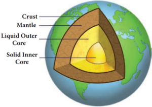
- However, it is believed that the Earth’s magnetic field is due to the molten charged metallic fluid inside the Earth’s surface with a core of radius of about 3500 km compared to the Earth’s radius of 6400 km.
Earth’s Magnetic Field:
- A freely suspended magnetic needle at a point on the Earth comes to rest approximately along the geographical north – south direction.
- This shows that the Earth behaves like a huge magnetic dipole with its magnetic poles located near its geographical poles.
- The north pole of a magnetic needle approximately points towards the geographic north (NG).
- Thus, it is appropriate to say that the magnetic north pole of the needle is attracted by the magnetic south pole of the Earth (Sm), which is located at the geographic north (NG).
- Also, the magnetic south pole of the needle is attracted by the magnetic north pole of the Earth (Nm), which is located at the geographic south (SG).
- The magnitude of the magnetic field strength at the Earth’s surface ranges from 25 to 65 micro tesla.
Maglev:
- Maglev train (Magnetic levitation train) has no wheels.
- It floats above its tracks due to strong magnetic forces applied by computer controlled electromagnets.
- It is the fastest train in the world.
- The speed attained by this train is around 500 km/hr.
Electric Motor:
- An electric motor is a device which converts electrical energy into mechanical energy.
- Electric motors are crucial in modern life.
- They are used in water pump, fan, washing machine, juicer, mixer, grinder etc.
- We have already seen that when electric current is passed through a conductor placed normally in a magnetic field, a force is acting on the conductor and this force makes the conductor to move.
- This is harnessed to construct an electric motor.
- To understand how a motor works, we need to understand how a current carrying coil experiences a turning effect when placed inside a permanent magnetic field.
- A simple coil is placed inside two poles of a magnet.
- Now look at the current carrying conductor segment AB.
- The direction of the current is towards B, whereas in the conductor segment CD the direction is opposite.
- As the current is flowing in opposite directions in the segments AB and CD, the direction of the motion of the segments would be in opposite directions according to Fleming’s left hand rule.
- When two ends of the coil experience force in opposite direction, they rotate.
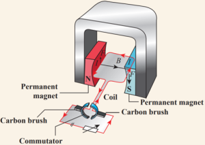
- If the current flow is along the line ABCD, then the coil will rotate in clockwise direction first and then in anticlockwise direction.
- If we want to make the coil rotate in any one direction, say clockwise, then the direction of the current should be along ABCD in the first half of the rotation and along DCBA in the second half of the rotation.
- To change the direction of the current, a small device called split ring commutator is used.
- When the gap in the split ring commutator is aligned with terminals X and Y, there is no flow of current in the coil.
- But, as the coil is moving, it continues to move forward bringing one of the split ring commutator in contact with the carbon brushes X and Y.
- The reversing of the current is repeated at each half rotation, giving rise to a continuous rotation of the coil.
The speed of rotation of coil can be increased by:
- Increasing the strength of current in the coil.
- Increasing the number of turns in the coil.
- Increasing the area of the coil and
- Increasing the strength of the magnetic field.
Electromagnetic Induction:
- When it was shown by Oersted that magnetic field is produced around a conductor carrying current, the reverse effect was also attempted. In 1831, Michael Faraday explained the possibility of producing an e.m.f across the conductor when the magnetic flux linked with the conductor is changed.
- In order to demonstrate this, Faraday conducted few experiments.
Faraday’s experiments:
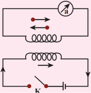
Experiment 1:
- In this experiment, two coils were wound on a soft iron ring (separated from each other).
- The coil on the left is connected to a battery and a switch K. A galvanometer is attached to the coil on the right.
- When the switch is put ‘on’, at that instant, there is a deflection in the galvanometer.
- Likewise, when the switch is put ‘off’, again there is a deflection – but in the opposite direction. This proves the generation of current.
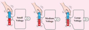
Experiment 2:
- In this experiment, current (or voltage) is generated by the movement of the magnet in and out of the coil.
- The greater the number of turns, the higher is the voltage generated.
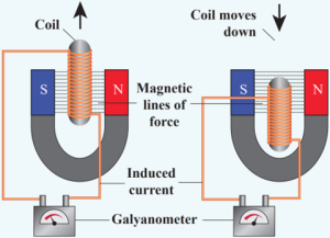
Experiment 3:
- In this experiment, the magnet is stationary, but the coil is moved in and out of the magnetic field (indicated by the magnetic lines of force).
- Here also, current is induced.
- All these observations made Faraday to conclude that whenever there is a change in the magnetic flux linked with a closed circuit an emf is produced and the amount of emf induced varies directly as the rate at which the flux changes.
- This emf is known as induced emf and the phenomenon of producing an induced emf due to change in the magnetic flux linked with a closed circuit is known as electromagnetic induction.
- Note: The direction of the induced current was given by Lenz’s law, which states that the induced current in the coil flows in such a direction as to oppose the change that causes it.
- The direction of induced current can also be given by another rule called Fleming’s Right Hand Rule.
Transformer:
- Transformer is a device used for converting low voltage into high voltage and high voltage into low voltage.
- It works on the principle of electromagnetic induction.
- It consists of primary and secondary coil insulated from each other.
- The alternating current flowing through the primary coil induces magnetic field in the iron ring.
- The magnetic field of the iron ring induces a varying emf in the secondary coil.
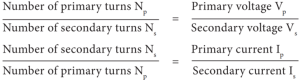
- Depending upon the number of turns in the primary and secondary coils, we can step-up or step-down the voltage in the secondary coil.
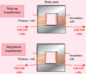
Step up transformer:
- The transformer used to change a low alternative voltage to a high alternating voltage is called a step up transformer. ie Vs > Vp.
- In a step up transformer, the number of turns in the secondary coil is more than the number of turns in the primary coil (Ns > Np).
Step down transformer:
- The transformer used to change a high alternating voltage to a low alternating voltage is called a step down transformer (Vs < Vp).
- In a step down transformer, the number of turns in the secondary coils are less than the number of turns in the primary coil (Ns < Np).
- The formulae pertaining to the transformers are given in the following equations.
- A transformer cannot be used with the direct current (DC) source because, current in the primary coil is constant (ie. DC).
- Then there will be no change in the number of magnetic field lines linked with the secondary coil and hence no emf will be induced in the secondary coil.
- Transformer is a stationary device used to transform electrical power from one circuit to another without changing its frequency.
- The applied alternating voltage is either increased or decreased with corresponding decrease or increase of current in the circuit.
- If the transformer converts an alternating current with low voltage into an alternating current with high voltage, it is called step-up transformer.
- On the contrary, if the transformer converts alternating current with high voltage into an alternating current with low voltage, then it is called step-down transformer.
Construction and working of transformer:
Principle:
- The principle of transformer is the mutual induction between two coils.
- That is, when an electric current passing through a coil changes with time, an emf is induced in the neighbouring coil.
Construction:
- In the simple construction of transformers, there are two coils of high mutual inductance wound over the same transformer core.
- The core is generally laminated and is made up of a good magnetic material like silicon steel.
- Coils are electrically insulated but magnetically linked via transformer core.
- The coil across which alternating voltage is applied is called primary coil P and the coil from which output power is drawn out is called secondary coil S.
- The assembled core and coils are kept in a container which is filled with suitable medium for better insulation and cooling purpose.
Working:
- If the primary coil is connected to a source of alternating voltage, an alternating magnetic flux is set up in the laminated core.
- If there is no magnetic flux leakage, then whole of magnetic flux linked with primary coil is also linked with secondary coil.
- This means that rate at which magnetic flux changes through each turn is same for both primary and secondary coils.
- As a result of flux change, emf is induced in both primary and secondary coils.
- The emf induced in the primary coil or back emf εp is given by
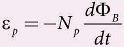
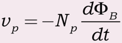
But the voltage applied vp across the primary is equal to the back emf. Then
- The frequency of alternating magnetic flux in the core is same as the frequency of the applied voltage.
- Therefore, induced emf in secondary will also have same frequency as that of applied voltage.
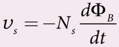
- The emf induced in the secondary coil εS is given by
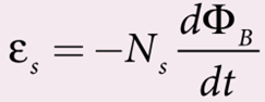
- Where Np and Ns are the number of turns in the primary and secondary coil respectively.
- If the secondary circuit is open, then εs = vs where vs is the voltage across secondary coil.
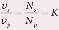
- This constant K is known as voltage transformation ratio. For an ideal transformer,
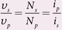
Input power vp ip = Output power vs is
- Where ip and is are the currents in the primary and secondary coil respectively. Therefore,
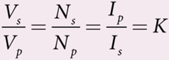
If Ns > Np (K>1), then Vs > VP and Is < Ip.
This is the case of step-up transformer in which voltage is increased and the corresponding current is decreased.
If Ns < Np (K < 1), then Vs < VP and Is > Ip.
This is step-down transformer where voltage is decreased and the current is increased.
Efficiency of Transformer:
- The efficiency η of a transformer is defined as the ratio of the useful output power to the input power. Thus
- Transformers are highly efficient devices having their efficiency in the range of 96 – 99%.
- Various energy losses in transformers will not allow them to be 100% efficient.
Energy losses in a transformer:
- Transformers do not have any moving parts so that its efficiency is much higher than that of rotating machines like generators and motors.
- But there are many factors which lead to energy loss in a transformer.
- i) Core loss or Iron loss
- This loss takes place in transformer core.
- Hysteresis loss and eddy current loss are known as core loss or Iron loss.
- When transformer core is magnetized and demagnetized repeatedly by the alternating voltage applied across primary coil, hysteresis takes place due to which some energy is lost in the form of heat.
- Hysteresis loss is minimized by using steel of high silicon content in making transformer core.
- Alternating magnetic flux in the core induces eddy currents in it.
- Therefore there is energy loss due to the flow of eddy current, called eddy current loss which is minimized by using very thin laminations of transformer core.
- ii) Copper loss
- Transformer windings have electrical resistance.
- When an electric current flows through them, some amount of energy is dissipated due to Joule heating.
- This energy loss is called copper loss which is minimized by using wires of larger diameter.
iii) Flux leakage
- Flux leakage happens when the magnetic lines of primary coil are not completely linked with secondary coil.
- Energy loss due to this flux leakage is minimized by winding coils one over the other.
Uses of Electromagnetism:
- Electromagnetism has created a great revolution in the field of engineering applications.
- In addition, this has caused a great impact on various fields such as medicine, industries, space etc.
- Speaker
- Inside the speaker, an electromagnet is placed in front of a permanent magnet.
- The permanent magnet is fixed firmly in position whereas the electromagnet is mobile.
- As pulses of electricity pass through the coil of the electromagnet, the direction of its magnetic field is rapidly changed.
- This means that it is in turn attracted to and repelled from the permanent magnet vibrating back and forth.
- The electromagnet is attached to a cone made of a flexible material such as paper or plastic which amplifies these vibrations, pumping sound waves into the surrounding air towards our ears.
- Magnetic Levitation Trains
- Magnetic levitation (Maglev) is a method by which an object is suspended with no support other than magnetic fields.
- In maglev trains two sets of magnets are used, one set to repel and push the train up off the track, then another set to move the floating train ahead at great speed without friction. In this technology, there is no moving part.
- The train travels along a guideway of magnets which controls the train’s stability and speed using the basic principles of magnets.
- Medical System
- Nowadays electromagnetic fields play a key role in advanced medical equipments such as hyperthermia treatments for cancer, implants and magnetic resonance imaging (MRI).
- Sophisticated equipments working based on electromagnetism can scan even minute details of the human body.
- Many of the medical equipments such as scanners, x-ray equipments and other equipments also use the principle of electromagnetism for their functioning.
Aurora Borealis and Aurora Australis:
- People living at high latitude regions (near Arctic or Antarctic) might experience dazzling coloured natural lights across the night sky.
- This ethereal display on the sky is known as aurora borealis (northern lights) or aurora australis (southern lights).
- These lights are often called as polar lights.
- The lights are seen above the magnetic poles of the northern and southern hemispheres.
- They are called as “Aurora borealis” in the north and “Aurora australis” in the south.
- This occurs as a result of interaction between the gaseous particles in the Earth’s atmosphere with highly charged particles released from the Sun’s atmosphere through solar wind.
- These particles emit light due to collision and variations in colour are due to the type of the gas particles that take part in the collisions.
- A pale yellowish – green colour is produced when the ionized oxygen takes part in the collision and a blue or purplish – red aurora is produced due to ionized nitrogen molecules.
Convert a galvanometer into an ammeter:
- Ammeter is an instrument used to measure current flowing in the electrical circuit.
- The ammeter must offer low resistance such that it will not change the current passing through it.
- So ammeter is connected in series to measure the circuit current.
- A galvanometer is converted into an ammeter by connecting a low resistance in parallel with the galvanometer.
- This low resistance is called shunt resistance S.
- The scale is now calibrated in ampere and the range of ammeter depends on the values of the shunt resistance.
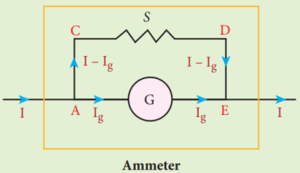
- Let I be the current passing through the circuit.
- When current I reaches the junction A, it divides into two components.
- Let Ig be the current passing through the galvanometer of resistance Rg through a path AGE and the remaining current (I – Ig) passes along the path ACDE through shunt resistance S.
- The value of shunt resistance is so adjusted that current Ig produces full scale deflection in the galvanometer.
- The potential difference across galvanometer is same as the potential difference across shunt resistance.

- Since, the deflection in the galvanometer is proportional to the current passing through it,
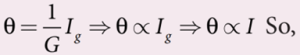
- The deflection produced in the galvanometer is a measure of the current I passing through the circuit.
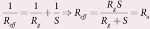
- Shunt resistance is connected in parallel to galvanometer.
- Therefore, resistance of ammeter (Ra) can be determined by computing the effective resistance, which is
- Since, the shunt resistance is a very low resistance and the ratio S / Rg is also small.
- This means, Ra is also small, i.e., the resistance offered by the ammeter is small.
- So, when we connect ammeter in series, the ammeter will not change appreciably the current in the circuit.
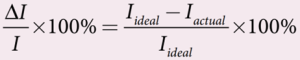
- For an ideal ammeter, the resistance must be equal to zero. But in reality, the reading in ammeter is always less than the actual current in the circuit.
- Let Iideal be the current measured by ideal ammeter and Iactual be the actual current in the circuit.
- Then, the percentage error in measuring a current through an ammeter is
Key points:
- An ammeter is a low resistance instrument and it is always connected in series to the circuit
- An ideal ammeter has zero resistance
- In order to increase the range of an ammeter n times, the value of shunt resistance to be connected in parallel is
Convert a galvanometer into a voltmeter:
- A voltmeter is an instrument used to measure potential difference across any two points in the electrical circuits.
- It should not draw any current from the circuit otherwise the value of potential difference to be measured will change.
- Voltmeter must have high resistance and when it is connected in parallel, it will not draw appreciable current so that it will indicate the true potential difference.
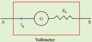
- A galvanometer is converted into a voltmeter by connecting high resistance Rh in series with galvanometer.
- The scale is now calibrated in volt and the range of voltmeter depends on the values of the resistance Rh connected in series i.e. the value of resistance is so adjusted so that current Ig produces full scale deflection in the galvanometer.
- Let Rg be the resistance of galvanometer and Ig be the current with which the galvanometer produces full scale deflection.
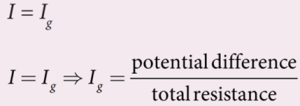
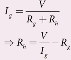
- Since the galvanometer is connected in series with high resistance, the current in the electrical circuit is same as the current passing through the galvanometer.
- Since the galvanometer and high resistance are connected in series, the total resistance or effective resistance in the circuit is the sum of their resistances.
- This gives the resistance of voltmeter. Thus the voltmeter resistance is
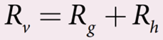
Therefore,
Note that ![]()
- The deflection in the galvanometer is proportional to current Ig.
- But current Ig is proportional to the potential difference.
- Hence the deflection in the galvanometer is a measure of potential difference.
- Since the resistance of voltmeter is very large, a voltmeter connected in parallel in an electrical circuit will draw least current in the circuit.
- An ideal voltmeter is one which has infinite resistance.
Key points:
- Voltmeter is a high resistance instrument and it is always connected in parallel with the circuit element across which the potential difference is to be measured.
- An ideal voltmeter has infinite resistance
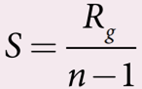
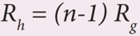
- In order to increase the range of voltmeter n times the value of resistance to be connected in series with galvanometer is
Eddy Current:
- According to Faraday’s law of electromagnetic induction, an emf is induced in a conductor when the magnetic flux passing through it changes.
- However, the conductor need not be in the form of a wire or coil.
- Even for a conductor in the form of a sheet or plate, an emf is induced when magnetic flux linked with it changes.
- But the difference is that there is no definite loop or path for induced current to flow away.
- As a result, the induced currents flow in concentric circular paths.
- As these electric currents resemble eddies of water, these are known as Eddy currents.
- They are also called Foucault currents.
Demonstration:
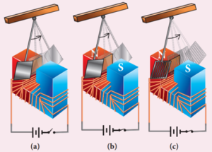
- Here is a simple demonstration for the production of eddy currents.
- Consider a pendulum that can be made to oscillate between the poles of a powerful electromagnet.
- First the electromagnet is switched off, the pendulum is slightly displaced and released.
- It begins to oscillate and it executes a large number of oscillations before stopping.
- The air friction is the only damping force.
- When the electromagnet is switched on and the disc of the pendulum is made to oscillate, eddy currents are produced in it which will oppose the oscillation.
- A heavy damping force of eddy currents will bring the pendulum to rest within a few oscillations.
- However if some slots are cut in the disc, the eddy currents are reduced.
- The pendulum now will execute several oscillations before coming to rest.
- This clearly demonstrates the production of eddy current in the disc of the pendulum.
Drawbacks of Eddy currents:
- When eddy currents flow in the conductor, a large amount of energy is dissipated in the form of heat.
- The energy loss due to the flow of eddy current is inevitable but it can be reduced to a greater extent with suitable measures.
- The design of transformer core and electric motor armature is crucial in order to minimise the eddy current loss.
- To reduce these losses, the core of the transformer is made up of thin laminas insulated from one another while for electric motor the winding is made up of a group of wires insulated from one another.
- The insulation used does not allow huge eddy currents to flow and hence losses are minimized.
Application of eddy currents:
Though the production of eddy current is undesirable in some cases, it is useful in some other cases. A few of them are
- Induction stove
- Eddy current brake
- Eddy current testing
- Electromagnetic damping
- Induction stove
- Induction stove is used to cook the food quickly and safely with less energy consumption.
- Below the cooking zone, there is a tightly wound coil of insulated wire.
- The cooking pan made of suitable material, is placed over the cooking zone.
- When the stove is switched on, an alternating current flowing in the coil produces high frequency alternating magnetic field which induces very strong eddy currents in the cooking pan.
- The eddy currents in the pan produce so much of heat due to Joule heating which is used to cook the food.
- Note: The frequency of the domestic AC supply is increased from 50–60 Hz to around 20–40 KHz before giving it to the coil in order to produce high frequency alternating magnetic field.
- Eddy current brake
- This eddy current braking system is generally used in high speed trains and roller coasters.
- Strong electromagnets are fixed just above the rails.
- To stop the train, electromagnets are switched on.
- The magnetic field of these magnets induces eddy currents in the rails which oppose or resist the movement of the train.
- This is Eddy current linear brake.
- In some cases, the circular disc, connected to the wheel of the train through a common shaft, is made to rotate in between the poles of an electromagnet.
- When there is a relative motion between the disc and the magnet, eddy currents are induced in the disc which stop the train.
- This is Eddy current circular brake.
iii. Eddy current testing
- It is one of the simple non–destructive testing methods to find defects like surface cracks, air bubbles present in a specimen.
- A coil of insulated wire is given an alternating electric current so that it produces an alternating magnetic field.
- When this coil is brought near the test surface, eddy current is induced in the test surface.
- The presence of defects causes the change in phase and amplitude of the eddy current that can be detected by some other means.
- In this way, the defects present in the specimen are identified.
- Electromagnetic damping
- The armature of the galvanometer coil is wound on a soft iron cylinder.
- Once the armature is deflected, the relative motion between the soft iron cylinder and the radial magnetic field induces eddy current in the cylinder.
- The damping force due to the flow of eddy current brings the armature to rest immediately and then galvanometer shows a steady deflection.
- This is called electromagnetic damping.
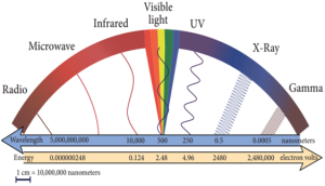
Electromagnetic Spectrum:
- Electromagnetic spectrum is an orderly distribution of electromagnetic waves in terms of wavelength or frequency.
Radio waves:
- They are produced by accelerated motion of charges in conducting wires.
- The frequency range is from a few Hz to 109 They show reflection and diffraction.
- They are used in radio and television communication systems and also in cellular phones to transmit voice communication in the ultra high frequency band.
Microwaves:
- It is produced by special vacuum tubes such as klystron, magnetron and Gunn diode.
- The frequency range of microwaves is 109 Hz to 1011
- These waves undergo reflection and can be polarised.
- It is used in radar system for aircraft navigation, speed of the vehicle, microwave oven for cooking and very long distance wireless communication through satellites.
Infrared radiation
- It is produced by hot bodies (also known as heat waves) and also by when the molecules undergoing rotational and vibrational transitions.
- The frequency range is 1011 Hz to 4 × 10¹⁴
- It provides electrical energy to satellites by means of solar cells.
- It is used to produce dehydrated fruits, in green houses to keep the plants warm, heat therapy for muscular pain or sprain, TV remote as a signal carrier, to look through haze fog or mist and used in night vision or infrared photography.
Visible light:
- It is produced by incandescent bodies and also it is radiated by excited atoms in gases.
- The frequency range is from 4 × 10¹⁴ Hz to 8 × 10¹⁴
- It obeys the laws of reflection and refraction.
- It undergoes interference, diffraction and can be polarised.
- It exhibits photo-electric effect also.
- It can be used to study the structure of molecules, arrangement of electrons in external shells of atoms.
- It causes sensation of vision.
Ultraviolet radiation:
- It is produced by Sun, arc and ionized gases.
- Its frequency range is from 8 × 10¹⁴ Hz to 1017
- It has less penetrating power.
- It can be absorbed by atmospheric ozone and is harmful to human body.
- It is used to destroy bacteria in sterilizing the surgical instruments, burglar alarm, to detect the invisible writing, finger prints and also in the study of atomic structure.
X-rays:
- It is produced when there is sudden stopping of high speed electrons at high-atomic number target, and also by electronic transitions among the innermost orbits of atoms.
- The frequency range of X-rays is from 1017 Hz to 1019
- X-rays have more penetrating power than ultraviolet radiation.
- X-rays are used extensively in studying structures of inner atomic electron shells and crystal structures.
- It is used in detecting fractures, diseased organs, formation of bones and stones, observing the progress of healing bones.
- Further, in a finished metal product, it is used to detect faults, cracks, flaws and holes.
Gamma rays:
- It is produced by transitions of radioactive nuclei and decay of certain elementary particles.
- They produce chemical reactions on photographic plates, fluorescence, ionisation, diffraction.
- The frequency range is 1018 Hz and above.
- Gamma rays have higher penetrating power than X-rays and ultraviolet radiations; it has no charge but harmful to human body.
- Gamma rays provide information about the structure of atomic nuclei.
- It is used in radio therapy for the treatment of cancer and tumour, in food industry to kill pathogenic microorganism.
The Types of Emission Spectrum:
- When an object burns, it emits radiations.
- That is, it emits electromagnetic radiation which depends on temperature.
- If the object becomes hot, it glows in red colour.
- If the temperature of the object is further increased, then it glows in reddish-orange colour and becomes white when it is hottest.
- The spectrum is called black body spectrum.
- It is a continuous frequency (or wavelength) curve depending on the body’s temperature.
- Suppose we allow a beam of white light to pass through the prism.
- It is split into its seven constituent colours which can be viewed on the screen as continuous spectrum.
- This phenomenon is known as dispersion of light and the definite pattern of colours obtained on the screen after dispersion is called as spectrum.
- The spectra can be broadly classified into two categories:
Emission spectra:
- When the spectrum of self luminous source is taken, we get emission spectrum.
- Each source has its own characteristic emission spectrum.
- The emission spectrum can be divided into three types:
(i) Continuous emission spectrum (or continuous spectrum)
- If the light from incandescent lamp (filament bulb) is allowed to pass through prism (simplest spectroscope), it splits up into seven colours.
- Thus, it consists of wavelengths containing all the visible colours ranging from violet to red.
- Examples: spectrum obtained from carbon arc and incandescent solids.
(ii) Line emission spectrum (or line spectrum):
- Suppose light from hot gas is allowed to pass through prism, line spectrum is observed.
- Line spectra are also known as discontinuous spectra.
- The line spectra consists of sharp lines of definite wavelengths or frequencies.
- Such spectra arise due to excited atoms of elements.
- These lines are the characteristics of the element and are different for different elements.
- Examples: spectra of atomic hydrogen, helium, etc.
(iii) Band emission spectrum (or band spectrum)
- Band spectrum consists of several number of very closely spaced spectral lines which overlap together forming specific bands which are separated by dark spaces.
- This spectrum has a sharp edge at one end and fades out at the other end.
- Such spectra arise when the molecules are excited.
- Band spectrum is the characteristic of the molecule and hence the structure of the molecules can be studied using their band spectra.
- Example: spectra of ammonia gas in the discharge tube etc.
Absorption spectra:
- When light is allowed to pass through a medium or an absorbing substance then the spectrum obtained is known as absorption spectrum.
- It is the characteristic of absorbing substance.
- Absorption spectrum is classified into three types:
(i) Continuous absorption spectrum
- When we pass white light through a blue glass plate, it absorbs all the colours except blue and gives continuous absorption spectrum.
(ii) Line absorption spectrum
- When light from the incandescent lamp is passed through cold gas (medium), the spectrum obtained through the dispersion due to prism is line absorption spectrum.
- Similarly, if the light from the carbon arc is made to pass through sodium vapour, a continuous spectrum of carbon arc with two dark lines in the yellow region are obtained.
(iii) Band absorption spectrum
- When white light is passed through the iodine vapour, dark bands on continuous bright background is obtained.
- This type of band is also obtained when white light is passed through diluted solution of blood or chlorophyll or through certain solutions of organic and inorganic compounds.
Fraunhofer lines:
- When the spectrum obtained from the Sun is examined, it consists of large number of dark lines (line absorption spectrum).
- These dark lines in the solar spectrum are known as Fraunhofer lines.
- The absorption spectra for various materials are compared with the Fraunhofer lines in the solar spectrum, which helps in identifying elements present in the Sun’s atmosphere.
Microwave Oven Works:
- Microwave oven works on the principle of torque acting on an electric dipole.
- The food we consume has water molecules which are permanent electric dipoles.
- Oven produces microwaves that are oscillating electromagnetic fields and produce torque on the water molecules.
- Due to this torque on each water molecule, the molecules rotate very fast and produce thermal energy.
- Thus, heat generated is used to heat the food.